The Problem
I have bought two cheap ESP32 based IoT development boards for around 30$, because the specs looked interesting:
- ESP32 based with 3D- wifi antenna
- 128x64 pixel OLED display
- LoRa Modem
This hardware has the potential to be a very versatile IoT prototyping (and even production) platform, but there was one drawback: You have to program it in the Arduino IDE. This means: You can do almost anything with it, but whenever you want to change something in the software then you have to recompile and upload everything.
I like the approach of NodeMcu better because there the ESP runs some scripting language which is interpreted, and therefore you can do even faster prototyping because
- you do not need to have a compiler toolchain installed (which is a massive advantage in the field) and
- you can do faster code-test-debug cycles (because all you have to change is a line in a script)
Well, it turned out that NodeMCU works escellent on ESP8266, and there is even a port to the ESP32 architecture, but my TTGO board is not supported. So I had to look for alternatives - and I found one of the best IoT operating systems so far: LuaRTOS
It promises everything I like at NodeMcu (like Lua as interpreter language, a comprehensive set of features around the ESP32 processor, a library for displays, one for LoRa Modems and so on), but my board was not in the list of the supported boards. So I had to compile it from scratch to support the TTGO ESP32 board.
The Solution
I built this solution on my Ubuntu 16.04 based laptop. Even if the provided information in this article may be useful on other OS too, keep in mind that software is being developed and things may change in the future. If you need support, please have a look at the LuaRTOS wiki and other online resources.
I used the commit: 663ef4d90bbbf1266ed0f1cf77ca61d8a548e925 of the software.
Step 1: Download LuaRTOS, install the toolchain and try to build anything
In the first step, I followed the instructions on the GitHub page how to build the software by yourself. The goal was (a) to understand what the building blocks of the software are, and (b) to verify that I can build a random version of this operating system on my machine.
I think the most important insights are:
- It's not enough to clone the LuaRTOS GitHub repository, because beside that (and the package build-essential and make) you need the esp-idf repository and the compiler for the ESP32 as well.
- The .env file ties all these things together
- If everything is set up correctly then you can build your software with the command make
- If the compilation was successful (sometimes this takes a while) the you can upload the new version wit the command make flash
- After that, you can connect to the ESP32 with any serial monitor. Here are my two favorites:
- Putty: sudo putty -serial /dev/ttyUSB0 -sercfg 8,1,N,115200A
- The ESP internal monitor: make monitor
In my first try, I choose the Generic ESP32 board, and it took about seconds to compile. After I have uploaded the image I was able to do everyday ESP32 stuff:
/ \_____/ \
/_____________\
W H I T E C A T
Lua RTOS beta 0.1. Copyright (C) 2015 - 2018 whitecatboard.org
build 1539538740
commit 663ef4d90bbbf1266ed0f1cf77ca61d8a548e925
Running from factory partition
board type GENERIC
cpu ESP32 rev 1 at 240 Mhz
spiffs start address at 0xf000, size 512 Kb
spiffs mounted on /
Lua RTOS beta 0.1 powered by Lua 5.3.4
/ > net.wf.scan()
SSID RSSI AUTH CH1 CH2
-------------------------------------------------------------
TestW1 -77 WPA_WPA2_PSK 6 0
HUAWEI-HA35-325836 -87 WPA_WPA2_PSK 6 0
Test9a -90 OPEN 6 0
/ >
Success! The ESP32 was up and running and it was able to accept commands. The provides shell is pretty powerful, and so I started to scan for nearby wireless networks and they were detected successfully.
Step 2: Get the display running
As next step, I want to get the built-in display up and running. Therefore the OS has to know (a) which type of display this is and (b) how it is wired to the ESP32. Both pieces of information can be looked up in the schematic of the board:
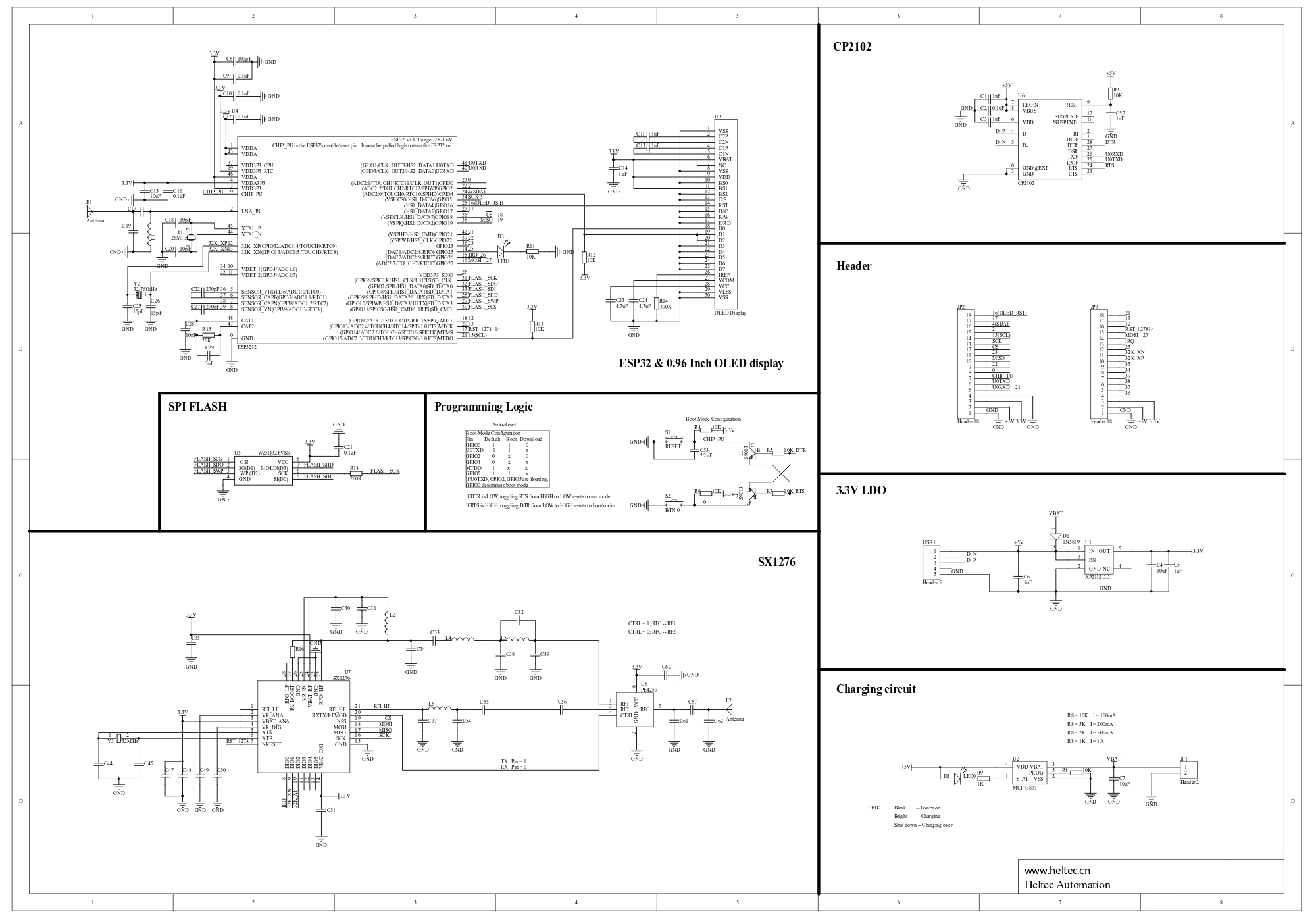
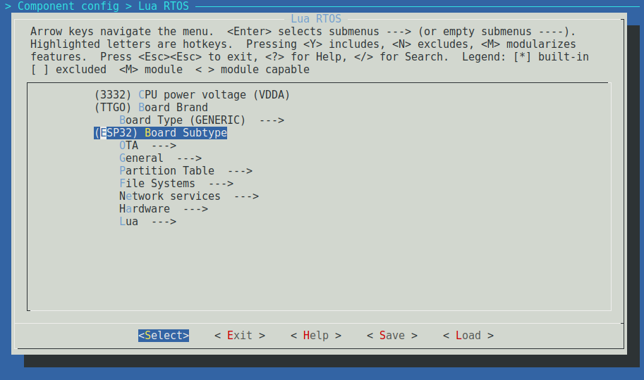
You can see that the display is connected via I2C, where the GPIO_15 is used as SCL and GPIO_4 is used as SDA. Precisely this information has to be provided to the compiler. An this is done similarly as in the Linux kernel. make menuconfig starts a ncurses-based graphical GUI where you can set all options for the operating system. Everything you need is in the menu Component Config > Lua RTOS
As a beginner lesson I started to enter the correct name for my board and its subtype:
After this initial lesson in dexterity I started to set the parameters for the display:
- Tell the OS that we want to use the I2C port number one by setting the following value:
Component config > Lua RTOS > Hardware > Graphic Display > I2C displays: Display I2C port = 1 - Set up the pin configuration for the I2C port number one (according to the schematic) by setting the following values
- Component config > Lua RTOS > Hardware > I2C pin map: I2C1 SCL = 15
- Component config > Lua RTOS > Hardware > I2C pin map: I2C1 SDA = 4
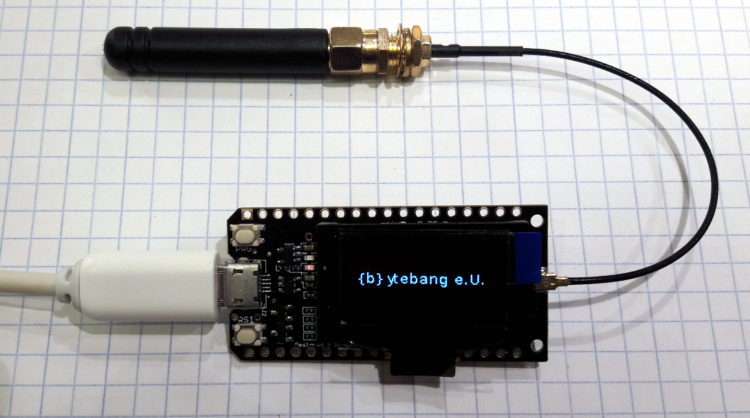
After this, you can exit the menuconfig and recompile and re-upload the whole thing. From now on you can use the graphics display as describes in the documentation. Here is a short snippet how to use it:
display_rst = 16
pio.pin.setdir(pio.OUTPUT, display_rst)
pio.pin.setlow(display_rst)
pio.pin.sethigh(display_rst)
-- Display something
gdisplay.attach(gdisplay.SSD1306_128_64, gdisplay.LANDSCAPE, false, 0x3c)
gdisplay.clear()
gdisplay.setfont(gdisplay.UBUNTU16_FONT)
gdisplay.write({gdisplay.CENTER,gdisplay.CENTER},"{b}ytebang e.U.")
And the result is:
Step 3: Get the LoRa modem running
Intro: LoRa is a license-free communication technology which enables users to send data to upper layer networks. One of these upper layer networks is TheThingsNetwork which is a fully distributed IoT data infrastructure. It is run by the public and private people and allows things to talk to the Internet without 3G or WiFi.
So the ultimate goal is to get this up and running. The approach is the same as before: You have to tell the operating-system which modem is connected to which pins - then you can use it. In make menuconfig I had to set the following values:
- We have to tell the OS that the modem is of the type sx1276
Component config > Lua RTOS > Hardware > LoRa Wan = sx1276, used in nodes and single-channel gateways - Since the modem is connected via SPI we have to set the correct GPIOs. We will use the third SPI channel for this.
Component config > Lua RTOS > Hardware > SPI pin map: SPI3 CS = -1
Component config > Lua RTOS > Hardware > SPI pin map: SPI3 MISO = 19
Component config > Lua RTOS > Hardware > SPI pin map: SPI3 MOSI = 27
Component config > Lua RTOS > Hardware > SPI pin map: SPI3 CLK = 5 - Now we have the SPI interface configured. We can assign the modem to it:
Component config > Lua RTOS > Hardware > LoRa Wan: LoRa SPI port = 3
Component config > Lua RTOS > Hardware > LoRa Wan: LoRa SPI CS GPIO number = 5 - Finally we are telling the LoraWan Modem which pin is responsible for the interrupt and the direct IO operations:
Component config > Lua RTOS > Hardware > LoRa Wan: LoRa RST GPIO number = 14
Component config > Lua RTOS > Hardware > LoRa Wan: LoRa DIO0 GPIO number = 26
Component config > Lua RTOS > Hardware > LoRa Wan: LoRa DIO1 GPIO number = 33
Component config > Lua RTOS > Hardware > LoRa Wan: LoRa DIO2 GPIO number = 32
We are done with editing. Finally, you need to recompile and upload the firmware one more time. Here is the example code which allows me to send data via LoRaWan:
lora.attach(lora.BAND868)
-- Activation via OOTA
lora.setDevEui("00101XXXXXXXXXXX")
lora.setAppEui("70B3DXXXXXXXXXXX")
lora.setAppKey("7E6F5XXXXXXXXXXXXXXXXXXXXXXXXXXX")
lora.join()
-- and transmit something
lora.tx(false,1,"AABB")
This script connects to the LoRaWan network and sends the information AABB. The result can be seen in the TTN console:
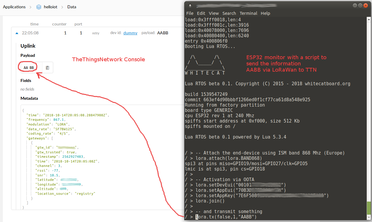
That's it. Thanks to this operating system I do not need to fire up an Arduino IDE to change a few instructions in the code. In one of my next articles, I am going to show you how to fetch and display data which is sent via TheThingsNetwork via MQTT.