My way to HAM radio
Since the age of 15 i wanted to to be a licensed HAM radio operator because radio fascinated me all the time. Unfortunately the motivation to do the exam to get the needed license was moderate because I thought had to visit a boring course and I had to learn Morse (CW) code to pass the exam. One day I stumbled across the OEVSV homepage page (= austrians ham radio association) and discovered that there was neither the need to learn cw code nor the need to visit a course to be approved to the A-class examination any more. Well at this point in time I ran out of arguments against myself and I decided to do this exam.
Since I have a very small amount of spare time I decided to learn the stuff by myself from books and online pages instead of visiting a course because "How hard can it be ?" ... To make a long story short: It can be hard if you are not interested in technical stuff but since I have a degree in electrical engineering the pure technical questions where simple to learn and understand. Of course there where a lot of new facts that I had to learn like wave propagation, operating modes, modulation schemes and so on, but in general this sparked more and more interest. And so I drifted away from learning the answers to the question towards a process of investigation and exploration of topics that are within the field of HAM radio or at least closely realted to it. This was actually the best that could happen to me. It showed me that the field of operation was much bigger than I had imagined it before. The legal stuff was acutally the hardest part for me to learn and understand because there is nothing that can be derived from facts or natures laws - I had to learn it by hard.
In December 2013 I finally took my exam in Graz and the telecommunication buerau assigned my my callsign OE6GUE.
Defining the requirements
At the same time as I decided to take the exam I started to look around what kind of station I wanted to have. The internet is full of ideas and instructions how to setup your first ham radio station but I wanted to have my very own station that satisfies all my needs. But then things started to be complicated because I had to answer a few questions by myself:
- What do I want to do with my station ?
- Where should I locate it ?
- Should it be portable ?
- How much should it be ?
- ...
To most of these questions I had no clear answer. So I decided to build a station that can be used in a lot of different usecases, on different locations and it sould work on different modes (from HAMNET to CW) in a lot of different bands. This was not an easy task because of the magic triangle of building a HAM radio station:
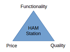
These triangles are known from the project management world an therefore often referred to as the "Project Management Triangle," where each side represents a constraint. One side of the triangle cannot be changed without affecting the others. In other words: "Quality, Functionality, Price -> pick any two".
Finally I decided to write down a list of things I am interested in and which are most likely to be tried out in the next few month / years. I complemented the list with a few functional requirements and the consequences of them.
| Requirement | Consequence |
|---|---|
| I want to be able to transmit and receive the following bands HF + 6m, 2m, 70cm | I have to look for a multiband / multimode tranceiver |
| It should be able to connect a computer to the station via CAT and via Soundcard to perform digital modes like PSK31 | Build / Buy a soundcard and CAT interface to the tranceiver |
| Since I am a open source guy I dont want to pay any license fees for the programs on the laptop | Use open source software under linux on a old laptop |
| I want to join HAMNET | I have to find (another) tranceiver that can be used in the 2.4GHz / 5GHz band |
| The station should be portable (at least I should be able to put it into my car within 10 Minutes - except the antennas) | Build it to fit into a box. Fix everything within the box because otherwise things will get damaged during transprotation. |
| It should be able to be powered rom AC mains or in case of an emergency from a plain car battery | Find a suitable power supply. |
| 100W of transmission power is enough | No PA neeeded. |
| I want to be able to connect self built antennas | Find a suitable antennatuner |
| It should not be too expensive | Build as much as you can by yourself - you have the license to do so ! |
| Ability to power 230V devices (such as phone chargers etc.) with a plain plug even when operated via a car battery | Need for an inverter (12V -> 230V) |
Choosing the components
Transceiver: After I had the list of requirments I started to see clearer and I began to search for a transceiver. With a lot of luck I found a used includng an , an external and an additional at ebay for less than 900 Euros including shipping - what a deal !
Power supply: One week later I had the radio in my hands and I discovered that I need a power supply for it. After a few hours of googling I decided to buy a Alinco DM-330MWII at a local HAM radio store (funkelektronik.at) because it provides enough power (30 Amps, 35 Amps peak), has a front panel display switchable to show voltage or current, Controls for voltage adjust and noise shift, terminal posts on rear panel, 2 sets of ush connectors and a single auto lighter socket on the front.
Laptop + Interface: After I had connected my old laptop via a car powersupply to the 13.8V bus I set up Ubuntu including all the ham packages. I was thinking about to build a CAT interface for the FT897d as well as a soundcard interface my myself but after a few hours of googling and reding reviews I decided to go with a because (a) it is not very expensive and (b) it must not be built by myself.
HAMNET: Regarding the HAMNET I decided to build a POE powered networkplug into my setup. The digitus POE Injector is connected to the 13.8V connector and the network interface of my laptop and can be used to drive which is connected to a 2.4 GHz WLAN Yagi that I have gotten as a present from one of my friends.
Antennas: Finally I had to choose two antennas for the radio. Since I (a) wanted to be portable and (b) I dont wanted to setup a antenna tower in my backyard I have choosen the following antennas:
- For HF + 6m: An JPole (bought at ebay) and
- For 2m and 70cm a dualband Slim-Jim from N9TAX (also bought at ebay)
I would say that the process of choosing the right components for my station took the most time because on the one hand side I had no expierience with those things (from a few things I did not even know if they are compatible) and on the other hand side I had no one to ask. So I read a lot of reviews in the internet (especially at eham.net). Whenever I ordered a part I had to make sure that I have not forgotten anything that locks out any other of my requirements. Regarding the order how I choose the components I can say that it was the bigegst luck to start with a transceiver - because this is one of the most important parts of a HAM station.
The final result
As last step I had to choose a housing for (nearly) all of the parts. I dont know why, but in my opinon my station had to be some kind of rack mount (porpably because I am working in the IT). I was searching for a small server housing but nothing I found fulfilled my needs to be durable but not too heavy to lift. One day I drove my working colleague home to his house and we talked about his last gig with his band - and then it hit me like a lightening: Why not use a 19" Rack like the musicans are using for their equipment. It turned out that a 5 unit rack fits my needs: Two shelfs for the equipment and a drawer for the laptop. Everything is in a box that can be closed from all sides and transported easily.
Since I am a fan of kepping things organized I decided to build a nice back panel where everything is routed to a proper connector. The power distribution (as well as the decision of the power source) is done via a cheap car fuse panel that distributes the power from the powersupply or the connector on the back side to the devices. I took me about 5 evenings to put all the things togehter and to wire the whole stuff beautifully but in the end I am very proud of the result.
If you want to see the images in a higher resolution klick ten files in the attatchments section.
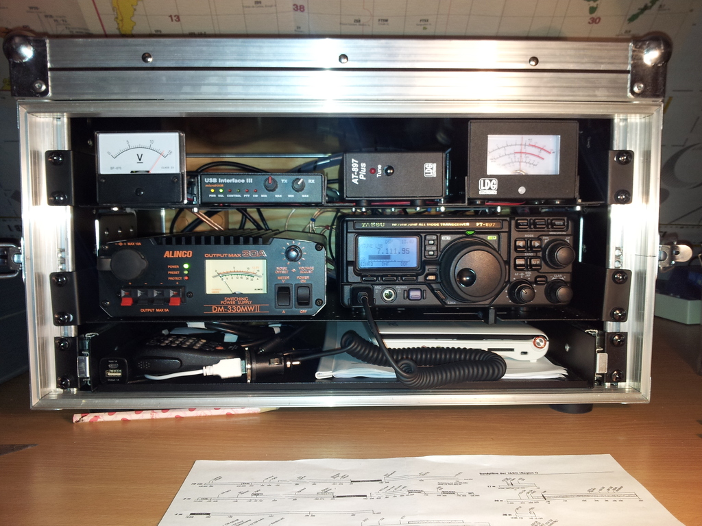 | This is the front-view of the shack. The devices from top left to bottom right are:
|
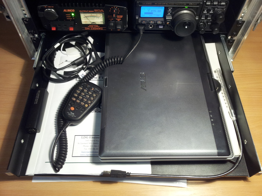 | Here you see the drawer with my laptop on it, The laptop can be powered via the built in laptop powersupply that converts 13.8V to 19V. |
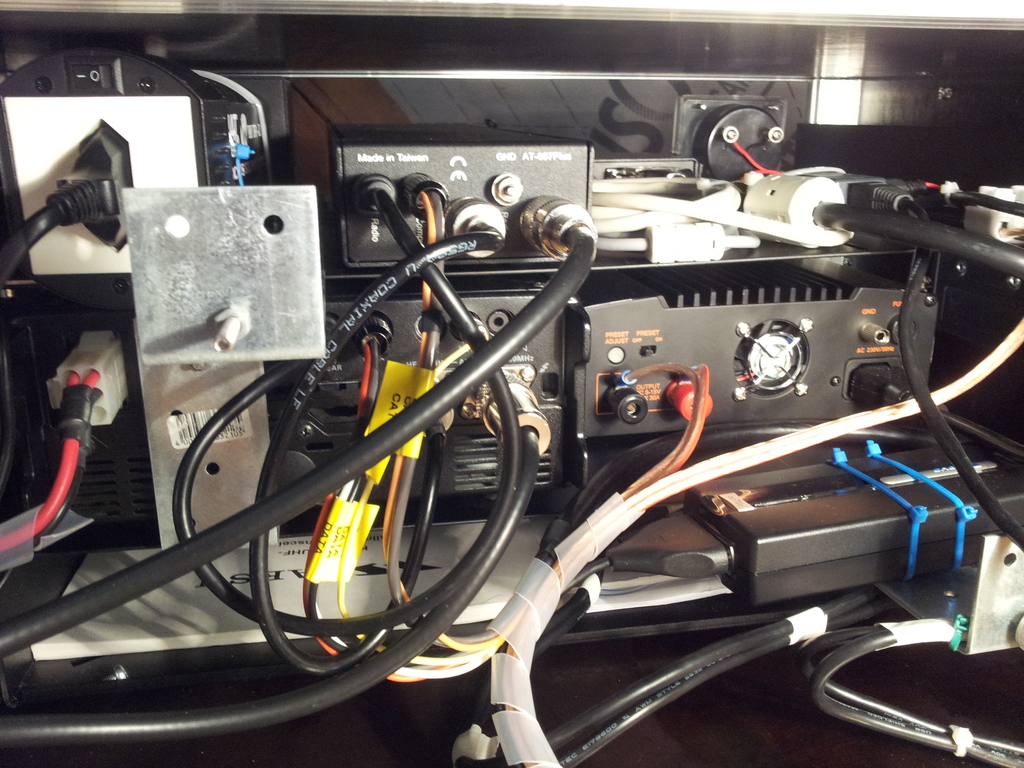 | A view from the back into the box. Tn the top left corner you can see the inverter that isa able to convert from 13.8V to 230V. In normal operation this is not activated. The next to the right is the antenna tuner followed by the Microham USB and its cabeling. No cables where shortened during the assembly and all cables are equipped with appropiate ferrites. |
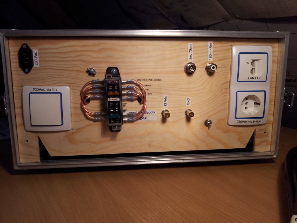 | This is the backside with the connectorpanel. In the top left corner you can see the powerplug for AC mains. The outlet with the cover ist the outlet which is driven by the inverter. Usually this is not used for anything, but iu thought that it would be nice to have in case on emergency to reload a mobildephone or something like that. The N and the PL connector in the upper middle area are the connectors to the antennas. The outlets on the left side are the POE capable LAN port for HAMNET. The outlet below the network socket is a plain plowerplug which is 1:1 connected to the AC mains conenctor. So the complete setup does not suck up a single puberplug if you take it with you. In the middle you can se the fusebox which is used as holder for spare fuses but also as a kind of switch where parts of the box can be taken from the 13.8V bus. The lower two fuses are used as input selector for the 13.8V bus. I can choose to power it from th powersupply but also from the both golden connectory right of the fusebox (or both). So this can also be used toprovide power to lab equipment. |
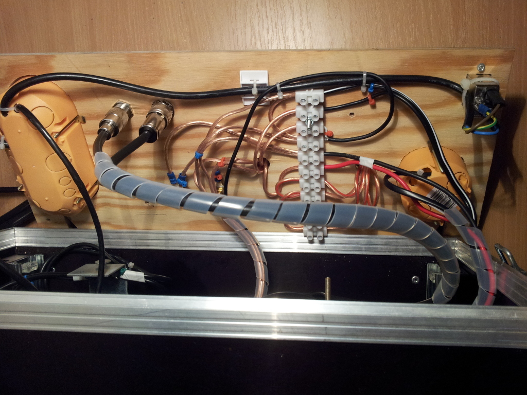 | This is the backside of the backpanel. You can see that the 13.8V bus is connected via 4 mm2 cables. In the right upper corner you can see a netfilter to prevent HF in the powerline. |
I hope you like it and if you have any questions or suggestions dont hesitate to ask me. Just leave a comment below this article.
73 de OE6GUE