The Problem
In summer 2015 I ordered the predecessor of this 3.5W laser diode with TTL modulation. My initial plan was to mount it onto my 3d printer - but we all know: plans are patient.
Lately I stumbled upon this diode in my junk box. I decided to finish the project and I ordered an Eleksmaker A3 frame (without Laser). It is big enough to engrave / cut things with a size of 300 x 400 mm.
A few weeks ago I had all the parts together and the journey could begin. It turned out that the online description how to assemble the frame is quiet good and it could be assembled within 2-3 hours.
Things became more interesting as I tried to attach my laser module onto the frame, because my laser and the delivered frame where physically incompatible, because my laser module has a separated power module which could not be mounted anywhere !
I also had no idea which software I should use (or can use - because I want to run it under Linux) and how tis software should be configured to work with the delivered Eleks Mana SE controller board.
The Solution
Hardware
After one sleepless night I decided to design and print a holder for the extra module.
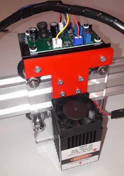
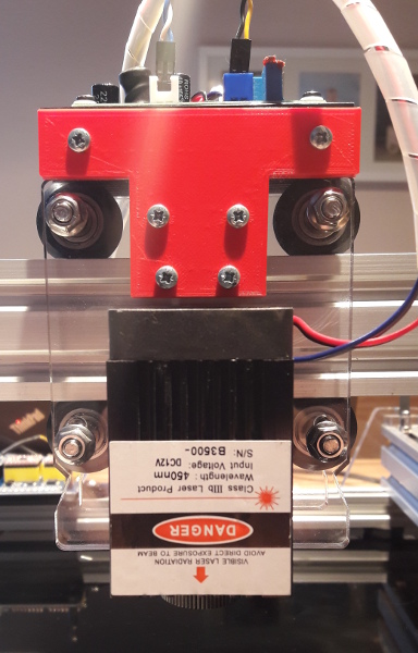
The advantage of this approach is, that there was no need to modify the laser or the acrylic part of the frame. All holes and threads were already there.
Cabling
The first issue was that the ManaSE controller-board came with a power supply which could not be used in Austria. So i decided to get a new one with 72W power (12V, 6A).
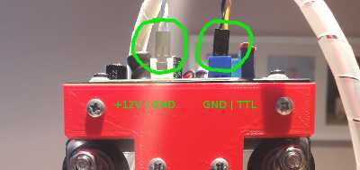
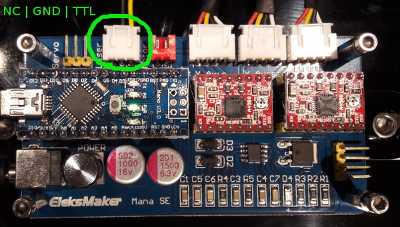
The next issue was, that the controller board has a 3-pin connector (the second from top left), but my laser has two 2-pin connectors.

It turned out that it was not that hard: One of the connectors of my laser board was straight forward: +12V | GND. The plugs that i have used I snapped of from the HDD Led and Reset Button from an old computer. Every other 2.54 mm (=100mil) connection jack should do as well.
I decided to power my laser-board independent from the controller-board. This has the advantage that the laser is being cooled if the board is turned of. Therefore I purchased an Y-Adapter that splits the power from the supply towards the controller board and (unswitched) to the white connector of the laser-controller.
The power setting for the laser comes in form of a TTL compatible PWM signal directly from the Pin 11 of the controller-board:
Since everything was cabled i decided to switch it on for the first time.
The reason behind this behavior is, that the Arduino nano (clone) which is used to drive the laser-board starts with a configuration where Pin 11 (=TTL PWM Signal for the laser) is in High impedance (Z) State until you connect the USB port to a computer.
If you want to prevent this (highly dangerous) behavior then you have to solder a 10kOhm pull down resistor between TTL and GND.
Software on the PC
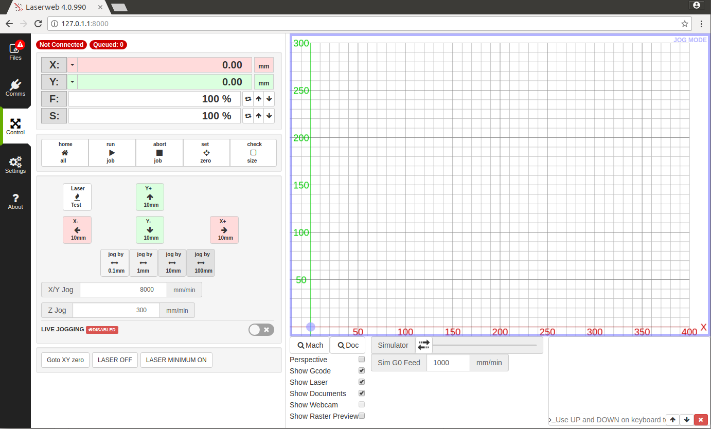
I was not happy that the delivered software (elekscam) did not run under Ubuntu. Therefore i had to find another CAM software which can be run under Linux. I found Laserweb 4.0.990. Even if there is an installer for the software i decided to pull the latest version from git.
The installation was pretty straight forward. I followed the instructions on the Laserweb wiki:
$npm -v
$node -v
$git clone https://github.com/LaserWeb/lw.comm-server.git
$cd lw.comm-server/
$sudo npm install serialport --unsafe-perm --build-from-source
$sudo npm install
$node ./server.js
A few moments later I fired up chrome and could start to work with the application:
Software on the Controller
Since i did not want to loose the original firmware i decided to swap the Arduino nano of the controller board for another nano-clone of this board with the GRBL 1.1f firmware flashed. This article shows how to flash the board.
Configuration
I don't want to go into each and every detail - but the following settings within the are working for me.
GRBL
I decided to go with the Laser mode of GRBL, because it supports adaptive power. The acceleration and maximum speed limits are empirically tested and set to ~85% of the maximum working value. Here are all the settings.
You can look up the meanings of the values in the configuration page of the GRBL wiki.
$1=25
$2=0
$3=2
$4=0
$5=0
$6=0
$10=1
$11=0.010
$12=0.002
$13=0
; Homing (not used)
$20=0
$21=0
$22=0
$23=0
$24=25.000
$25=500.000
$26=250
$27=1.000
; Spindle settings
$30=255
$31=0
; Laser mode ON
$32=1
;Steps
$100=80.000
$101=80.000
$102=80.000
;Max rates
$110=15000.000
$111=8000.000
$112=0.000
; Accelerations
$120=10000.000
$121=2000.000
$122=0.000
; Max travel (not used)
$130=2000.000
$131=2000.000
$132=2000.000
Laserweb4
The usage of the laser within g-code is simple:
- M3 turns the laser on (with constant power),
- M4 turns the laser on with adaptive power,
- M5 turns the laser off.
- S1 - S255 sets the power of the laser (0 - 100%)
I created a new profile (EleksMaker_A3) which can be imported into Laserweb with Settings -> Tools -> {Settings, Machine Profiles} Load
Results & Conclusio
After working for a few hours with the setup I can say that i does what it is supposed to do.
- The quality of the Eleksmaker Frame and controller is good.
- The results are (if you have figured out the parameters) quiet OK.
- You have to get used to the procedure how to engrave things
- Create your text / drawings within InkScape - Don't forget to convert objects to paths.
- Import it into Laserweb
- Enable / Disable the tings you want from the imported svg
- Add operations to the paths
- 300 mm/min + 100% Power cuts easily through paper.
- 60mm/min + 100% Power cuts cardboard
- Use lower power on dark plastics - it melts !
- Jog to the 0 point and set it
- Turn the Laser to minimum on (1%) and check the size with goggles
- Press run and wait till it is finished
- Cuts are way nicer with the M4 instead of the M3 command. This is because LaserWeb sometimes takes its time till the next G Code is sent. Meanwhile the laser would produce a hole.
- Universal G-Code Sender works also very well for sending the generated gcode. The laser does never ran run out of instructions (in contrast to Laserweb where this sometime happens) .
- It is important to wear safety goggles. Also if you do not directly look into the beam :-)
- I can engrave
- Wood
- Plastics
- Paper
- Sponge
- Rubber
- ...
- I can cut
- paper (single pass)
- cardboard (single pass)
- cellular rubber (multi pass)
- More power would be nice - but also more dangerous.