The problem
This spring I decided to build a FLARM base station with my old Raspberry Pi. The Open Glider Network is a good starting point for this purpose. The OGN is a community project. It is based on software, hardware, receivers and other contributions from individuals and the open source community. The objective of the Open Glider Network is to create and maintain a unified tracking platform for gliders and other GA aircraft. Currently OGN focuses on tracking aircraft equipped with FLARM, FLARM-compatible devices or OGN tracker. FLARM is mainly utilized in gliders, however other small aircraft (planes, helicopters, deltas or even para-gliders) are also often equipped with it, especially if operating in the areas intensively used by gliders, such as the Alps.

Such a device costs usually less than 100€) and adds some safety to our local glider club, because the approach an be coordinated better if you know the exact position of all the aircraft in the vicinity. All you need is a Raspberry PI (I would recommend a RPIv2 for this - especially if you want to use your Rpi as webcam too), a rtl-sdr compatible DVB-T stick some enclosures, a power supply and a internet connection. Of course you will need an antenna as well. You can use all antennas that you would use with your FLARM device, or you can build one by yourself. Since FLARM antennas are expensive I decided to build my own antenna.
The solution
A quick internet research revealed that the European version of FLARM system uses a data communication frequency in the free Non-Specific Short Range Device (SRD), sub band f, between 868.0 ?and 868.6 MHz. The ERP power is less than 10 mW (duty cycle 1%). This band is ruled for European applications in the documents ERC/REC 70-03 annex 1(f) and ERC/DEC/(01)04.
So everything I need is an easy to build, cheap, omnidirectional receiving antenna that is resonant on exactly this frequency: In other words a vertical polarized ground plane antenna.
Step 1: Choose the parts
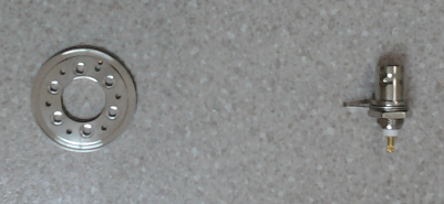
If something should be really cheap then it is always a good idea to work with something you have. I had a look into my junk box where I found everything that is needed to build a ground plane antenna: An old BNC connector and a ring from an old hard disk should do the trick.
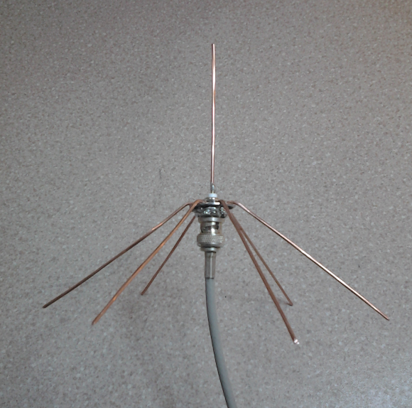
Step 2: Assemble the antenna
This was simple as 1,2,3:
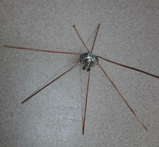
- Cut of seven pcs. of copper wire. I have used 1.5 mm2 wire that is usually used in house installations.
- Stretch and adjust them that they are straight an approx 20cm. long
- Solder six of wires to the ring
- Attach the BNC connector to the ring
- Solder the remaining wire to the center of the BNC connector
- Bend down the radials (the exact angle is determined in the next step)
 |  |
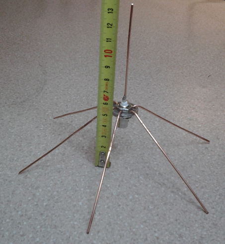
Step 3: Tune the antenna
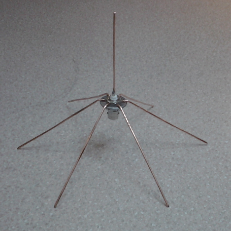
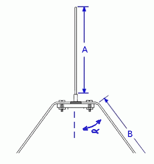
Now we have something that looks like a ground plane antenna. The next step was to measure the impedance and resonance frequency of the antenna and to tune everything till it is resonant in the 868 MHz Band. This can be done with a Vector Network Analyzer like the miniVNA with the frequency extender. I did a couple of measurements to find the correct length of all the elements:
| A [mm] | B [mm] | min SWR | @ | f [MHz] |
|---|---|---|---|---|
| 167 | 141 | 1.7 | @ | 438 |
| 160 | 141 | 1.4 | @ | 439 |
| 130 | 141 | 1.1 | @ | 520 |
| 100 | 141 | 1.3 | @ | 620 |
| 100 | 120 | 1.1 | @ | 650 |
| 100 | 110 | 1.0 | @ | 680 |
| 80 | 90 | 1.1 | @ | 836 |
| 75 | 90 | 1.1 | @ | 868 |
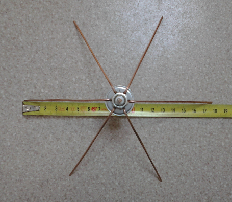
This is the final result:
 |  |
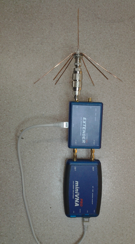
And here are some images of the measurement setup:
 | 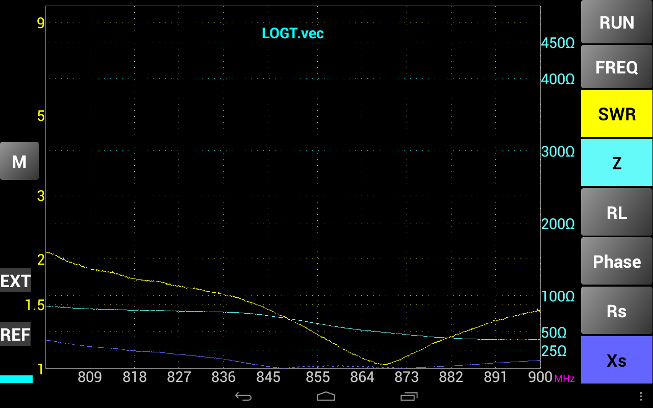 |
The results show that the antenna has its minimum SWR of nearly 1.0 @ f=868 MHz at an impedance of about 50 Ohm - which is the best possible case.
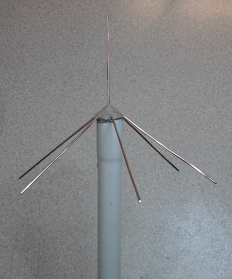
Step 4: Make it waterproof
Since the antenna will be mounted outside the last step was to make the whole thing waterproof. Some hot glue and a installation tube did the trick.
 |  |
Since the antenna cable will not be very long i decided to choose an old 10Base-T Coax cable with 50 Ohm. If your antenna cable will be longer than 1m then
consider buying a Aircell-5 or something similar to prevent losses within the cable.
73, OE6GUE