The problem
As a part time motor pilot in our aviation club ASFC Leoben I decided on a hot summer day where i had to wear the sweat soaked one-for-all headset in our DR48 to buy my own headset. It had to be one with active noise reduction that is comfortable to wear and it had to have a bluetooth interface for accepting calls during long flights. After reading some reviews and after trying some of them I went with the . Even after hours of wearing this headphones i did not have headache or any other complaints and so the choice was perfectly right.
Beside my activities as pilot i am teaching at the FH JOANNEUM (universtiy of applied sciences) in the department of applied informatics. Along with some face-to-face sessions with my students i also teach them online via teamspeak and vnc. So the need for another comfortable headset (or an adapter for my aviation headset) emerged. Tht initial idea was to buy such a thing (like the adapter of flightsounds) but 75$ are a little expensive. So i decided to roll my own adapter with the same functionality.
Technical details + schematic
From a techical point of view the most important difference between a normal headset and an aviation headset are the different plugs. In aviation we are not using the plain 3.5 mm2 Jacks that are known from PC / Gamerheadsets - we are using something that is not that fragile:
|
|
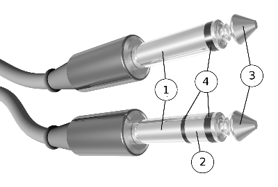
Commercial and general aviation (GA) civil airplane headset plugs are similar, but not identical. A standard 1?4 in monaural plug, type PJ-055, is used for headphones, paired with special tip-ring-sleeve, 0.206 inch diameter plug, type PJ-068, for the microphone. On the microphone plug the Ring is used for the microphone 'hot' and the sleeve is common or microphone 'Lo'. The extra (tip) connection in the microphone plug is often left unconnected but is also sometimes used for various functions, most commonly an optional push-to-talk switch, but on some aircraft it carries headphone audio and on others a DC supply
So the first step was to find suitable jacks - namely: PJ-055 and PJ-068. Fortunately i had some of them laying around in my hardware box. The next step was to find a small USB soundcard that is cheap, has a good quality and that can be opened without beeing destroyed. I decided to buy a very cheap USB soundmercard at a local distributor around the corner. The last step was to wire everything togehter. After a small internet research i decided to do it like this:
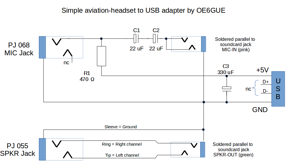
The schematic is really simple: On the left side there are the connectors that are needed to plug the headset in. on the right side you can see connectors of the USB soundcard. In the lower area you see the speaker cabeling and in the upper half the schematic for the phantom power of the headset microphone. (According to the RTCA Inc. standard DO-214, phantom power (8 to 16 volts DC in series with a 470 ohm resistor) is used to drive aviation microphones). The microphone is powered with the USB supply voltage of +5V which is indeed lower than the suggested 8-16 Volts but it works fine. R1 is the before mentioned resistor and C1+C2 are building a DC blocker towards the soundcard.
C3 is optional. It is used to suppress noise on the USB bus because on my older laptop the DC supply voltage on the USB bus had a small ripple which could be heard as annoying hum in the headphone.
Special thanks to Mark Wundrak and Hartwig Woellstein who pointed out some errors in the initial version of this schematic.
Result
It took me approx. 6 hours to build the whole thing (including the housing) and it works very well. The overall costs for this project was at about 15€ because i had some of the jacks and the housing already at home. Here are some pictures of my adapter:
 | This image shows the backside of the adapter. On the left side you can plug in any common aviation headset. |
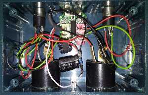
| Here you can see whats inside the box. The actual wiring according to the schematic above. On the bottom you see the two big jacks for the aviation headset (Left: PJ068 for the headphones / speakers, Right PJ055 for the microphone). In the upper area you can see the opened soundcard where the connections are coming from and going to. The cabeling was made with 0.5 mm2 copper wire which is usually shipped with breadboards. The meaning of the colors is as follows:
|
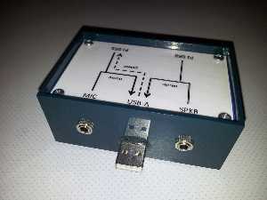 | As you can see i have pasted the soundcard into the housing. To be able to use it without my aviation headset (for example as backup soundcard for my laptop) I mounted two additional jacks on the frontside. These are plain 3.5mm stereo jacks where i can plug in any other conventional computer headset. These plugs are in parallel with the plugs that are on the soundcard. |