The Problem
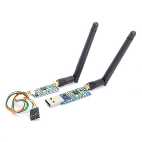 | I recently bought a radio telemtry kit from a friend who wanted to use it for his do-it-yourself drone project. One side is connected to the computer and shows up as a serial USB port. The other side has a TTL serial interface. The main purpose of the HM-TRP from 3D Robotics is to provide a transparent serial link over the air. My buddy sold it because the plugs did not fit into the ardupilot board. As it turned out it is a 915 MHz telemtry kit hich was bought in US and which is forbidden in the european union because it viloates the frequency regulation. In Austria the 915 MHz frequency is assigned to the GMS opertors, and it is not allowed to transmit on these frequencies. By law there would be a penalty up to a few thousand euros is somebody catches me operating this thing. As a licensed HAM radio operator i was searching for a way how to modify this TRX to be able to operate it in the 70 cm Band. |
The Solution
As it turned out both sides of the telemetry kit are using a HM-TRP 100 mW transceiver module to transmit data over the air. After an hour of analyzing the board an googling around i stumbled upon a forum post that describes how to change the operting frequency of HM-TRP 3DR Radio for Telemetry using AT Commands.
MHefny discovered that the original SiK Source code has an internal variable that specifies the operating freqency of the HM-TRP module. Unfortunately this variable is hardcoded in the default firmware image. He forked the project and added a 16th configuration variable to the available EEPROM settings. This variable can be changed via AT commands and modifies the operating frequency of the module. The following few sections describe how to flash the modules and how to test if it has worked.
In a lot of countries it is illegal to modify transmitters without a HAM radio license. So if you want to modify yours by applying the steps provided below - be sure not to viloate any given law in your country !
Step 1: Download the correct software
You will need two parts of software:
- The first one is the patched firmware that contains the additional 16th configuration variable. You can either compile the firmware by yourself or you can download the compiled firmware image from here or from the original post.
- The second software is a tool which is able to put the alternative firmaware onto the board. Since i prefer linux as operting system i looked around for a firmware that can be run from ubuntu or one that can be emulated via wine, but unfortunaltely no one seemed to work. In the end i choose I choose the HM-TRP config tool that was suggested in the arducoper-wiki and i ran if from a windows7 computer.
After you have plugged in the PC part of the HM-TRP radio in the USB port you have to make sure that the usb drivers are installed. Unsually this is not an issue on Win7. The drvice should show up in the devide manager as USB Serial device. After that you can unzip the installation directory of the HM-TRP config tool and run the 3DRRadio.exe. If you have multiple serial ports connected be sure to select the correct one in the top left corner. The connection speed is per default is set to 57600 baud.
Step 2a: Flash the PC module
The next step ist to put the new firmware onto the pc module. This is quiet simple:
- Press "Upload Custom Firmware"
- Select the patched firmware image (*.hex)
- Confirm it
- Wait till it says Success
This was the easy part.
Step 2b: Flash the remote module
I am not sure if it is possible to flash both devices at once but even if it would be possible then it would need to transfer the hex file over the air - which utilizes the 915 MHz band, which makes it illegal in Austria. So i went with another solution. Since the TTL part could not be connected to USB directly i wrapped up a cheap USB2Serial connector and a Serial2TTL level shifter (based on the famous MAX232) to a breadboard.
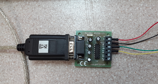 | 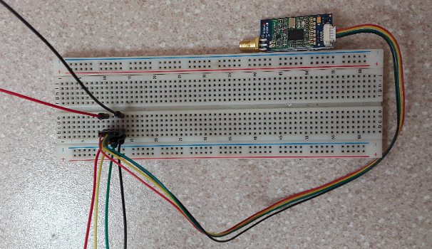 |
| This is my chumbersome USB <-> RS232 <-> TTL converter | ... which was connected to the module. |
After that flashing the firmware was the same procedure as before:
 |  |
| The original firmware was set to 915 MHz | After flashing the firmware was set to 433 MHz |
Step 3: Verify that it works
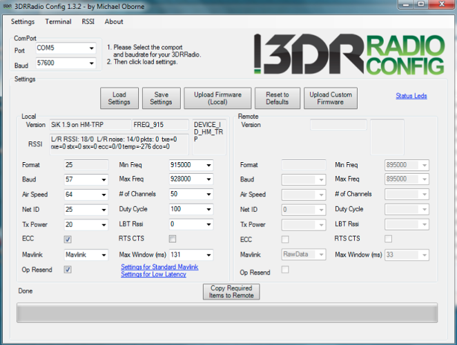
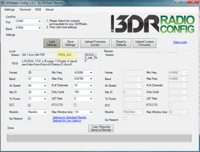
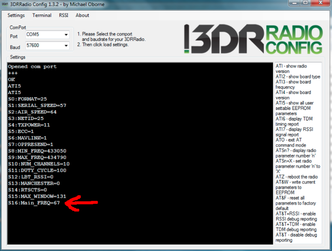
Now it was time to verify that everything works. First i read out all configuration parameters. The new configration parameter (#16) was available. By default it was set to 433 MHz:
This new parameter enables the user to select the frequency range that should be used by the module. Possible values (according to the firmware sourcecode) are:
{
FREQ_433 = 0x43,
FREQ_470 = 0x47,
FREQ_868 = 0x86,
FREQ_915 = 0x91,
FREQ_NONE = 0xf0,
};
In the screenshot the value of ATS16 is set to 67 ... which is 0x43 in hex ... which means that the module transmits and receives in the 433 MHz band -> Perfect.
But sometimes software lies to the user. So i fired up my old scanner to be sure that the traffic was really around 433 MHz:
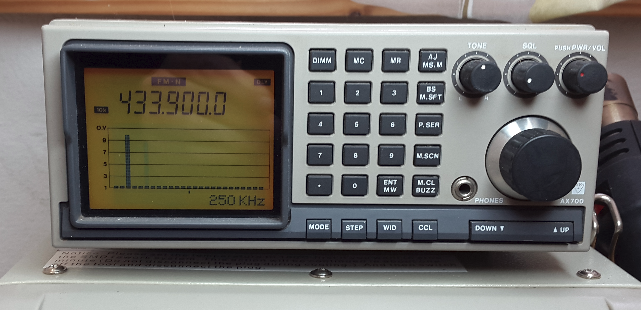
This also seems to be ok. The last step of verification was to transmit data between the two modules. Since i did not have a specific test case i decided to connect RX and TX on the TTL side. Every byte that was transmitted over the module would be received by the TTL part. The connection between the TX and the RX pin on the TTL side ensures that the received data is transmitted back to the origin. To make a long story short: Everything that was transmitted by the terminal was received back.
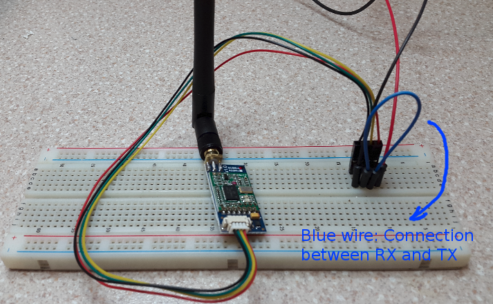 | 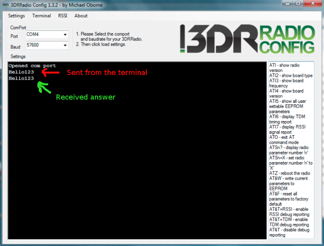 |
| The connection between RX and TX on the client side | Terminal repeats everything you send |
Why it is not that trivial to switch from 915 to 433 MHz (70cm)
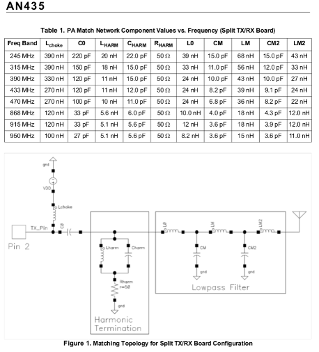
A detailed look into the specification of the HM-TRP board reveals that it it sutilizing the Si1000 radio which is a "MCU with Integrated 240–960 MHz EZRadioPRO Transceiver". The datasheet of the Si1000 tranceiver suggests that it can be tuned from 240–960 MHz - but according to the application note 427 (Rx LNA matching) and the application note 435 (PA Matching) the R, C and L values of the matching filters have to be adjusted to the used frequency to reduce spurious transmissions.
This means that there could have some unwanted byproducts in the transmission which could be again violating given law if they are not attenuated by -60db in respect to the peak envelope power. To ensure that this is not the case i tried the following: Within a shielded room i let Let the HM-TRP send arbitrary data (cat /dev/urandom > /dev/ttyUSB0 ) and look what harmonics are present. Since i do not have a GHz spectrum analyzer at hand i fired up my USRP N210 with a WBX doughtercard which can be used to monitor a bandwith of 25 MHz simultanously. These are the results of the measurement with the uncalibrated USRP (Screenshots are from uhd_fft).
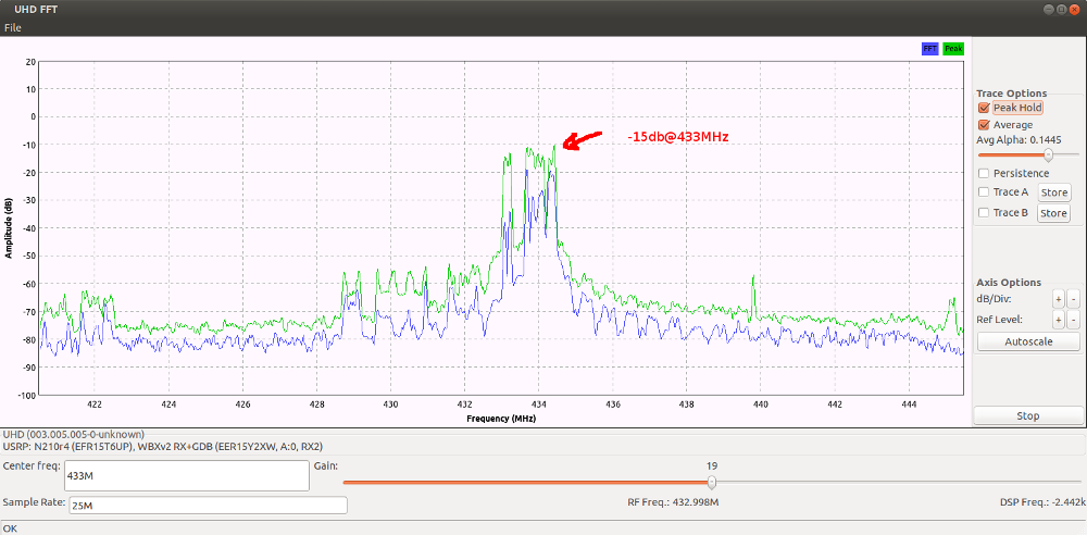
We can see that the receiver gets the transmitted signat with peaks around -15db @ 433 MHz.
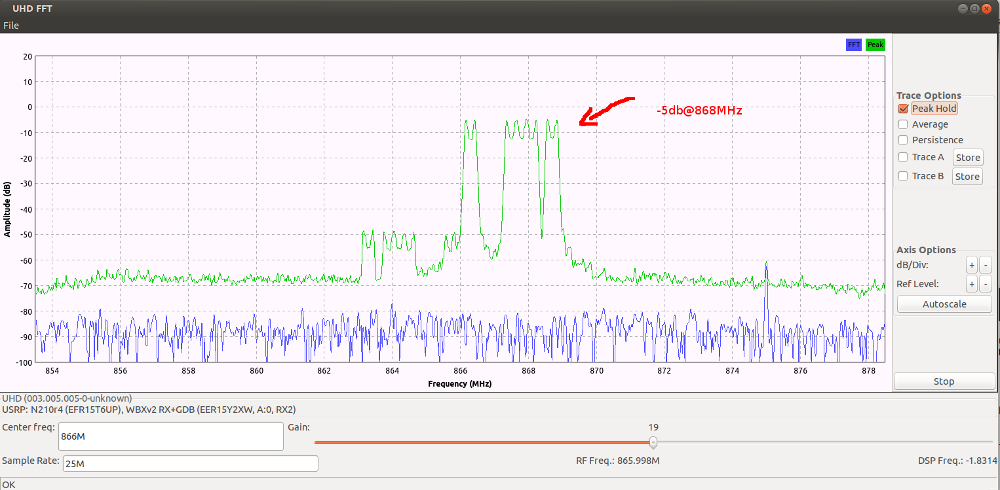
This one is the proof that we are not allowed to operte the device. At the double frequency (433 * 2 = 866 MHz) we can see peaks at -5db! Thats 10x stronger than the original transmitted signal - which is a clear indication that the matching filter circuit is not working for the changed frequency of 433 MHz.
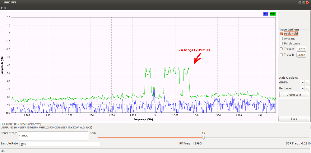
At the third harmonic (3 * 433= 1299 MHz) we can still observe the significat pattern of the transmission. We can see that 43-15= 28 db attenuation is too less to operate this thing legally (by law we would require less than 60db attenuation) .
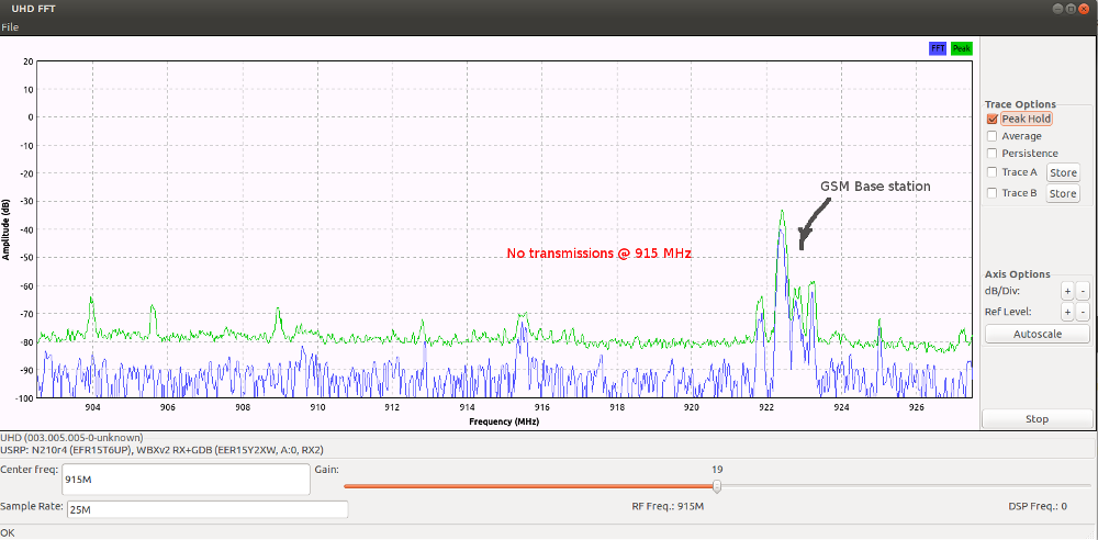
The good news are that there are no spurious transmissions in the 915 MHz range. So the GSM operators can be happy.
Switching from 915MHz to into the SRD Band (868MHz)
While the last results are not really satisfying i decided to start another attempt. I reconfigured the module again to swith it to the SRD band. To be more precise: I configured the module to the following settings:
- Dutycycle < 10%
- 869,4 Mhz < frequency < 869,65 MHz
- 10 Subchannels
- 11 dBi output power
With this new settings the device is transmitting in the SRD band which is 46 MHz below the original frequency of 915 MHz. The difference between the original frequency and the new one is now ~ -5% of the original frequency. The tolerance of the used parts in the matching circuit may be higher - so i have a chance that this will work without negative effects. It turned out that this works very well:
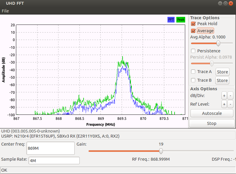
The screenshot shows that the transmitter is using the correct frequency.
This time the filter network seems to work better. At the doubled frequency we can still see some spikes, but they are attenuated by ~ -60db ... which means that the spurious transmissions are 1.000.000 times weaker than the original signal.
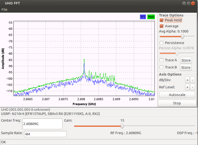
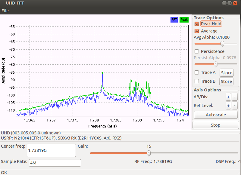
At the frequency of the thrid harmonic (3 * 869.5 = 2608 MHz) we can still see some spurious transmissions, but they are already fading into the noise floor.
Summary
It is easy to reflash the HM-TRP radio with another firmware that enables the user to select the operating frequency via an AT command. On the first view everything seems to work but according to the measurements i would expect poor / degraded perfomance if you operate a 915 MHz device at 433 MHz. However the measurements with an uncalibrated USRP N210 revealed that it is illegal to operate it without modification of the matching network or without adding an additional band pass filter.
The measurements with another reflashed HM-TRP that was transmitting at 868 MHz suggests that this setup leads to better results because the difference of the operting frequencies around 5% and therefore the matching network is not THAT misaligned. Be warned: Even if now the regulations are fulfilled it is still illegal to operate a modified transmitter because:
- As a normal person you are only allowed to operate CE equipped stuff that is conform to the regulations. Any modification of the device is illegal and invalidates the CE certificate.
- As a HAM radio operator you are allowed to modify the TRX but you are only allowed to use it within HAM radio bands. So the only legal usage would be to set it to 433 MHz (or somewhere else in the 70cm band) and to rework the matching circuit. If you dont rework the matching circuit (its completely made of tiny SMD parts) then you would have to attatch a bandpass filter for the 70cm band.
73, OE6GUE