The Problem
A colleague who is restoring an old-timer bus asked me if I know where to get an electronic circuit that is able to dim two different lights - but with just one knob. The reason behind this is that the old-timer bus has only one mounting hole left in its dashboard. He reported that they tried to build such a circuit wit a potentiometer (out of an old radio), but without success. So it became my task to design such a circuit.
The first step was find out why their approach did not work. So I asked him to draw a schematic of what they tried out. We figured out that the did not want to dim a single lightbulb - they want to dim 8 lightbulbs (connected parallel to each other) in each channel. After that it was completely clear why they failed: The potentiometer could not handle the power of nearly 100W and burned out.
The Solution
Beside the fact that the potentiometer could not handle such a high current, it is not a good idea to dim lights with a series resistor, because the series resistor is exposed to the full current - which produces heat. We want light - and not heat.
The solution to this is to build a PWM circuit.
What is PWM ?
PWM is the abbreviation for pulse-with-modulation. Imagine it as follows: You have a switch that is able to turn your light on and off very fast (a few hundred times per second). The percentage of the time where the light is turned on becomes linear to the lightness of the bulb. Look at the following figure:
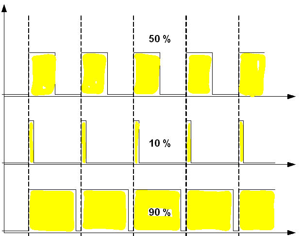
The light is turned completely on or completely off. In the top diagram the duty-cycle is 50%. This means that the light is turned on as long as it is turned off. In the middle the duty cycle is 10% - which means that the light is turned on only for 10% of the time. If the light is turned on and off for more than 25 times per second the human eye can not see it flickering any more. It sees just a light with a certain brightness. This is why PWM is a good approach to dim lights:
- If you switch fast enough then the light appears as non flickering
- You do not need to waste energy on a series resistor, because turning completely on and of is enough.
How to create a PWM circuit ?
There are different circuits how to create a simpme PWM circuit. They range from a simple NE555 to full blown micro controller circuits. All of them have one thing in common: They use a transistor to switch a current very fast on and off. The duty cycle corresponds then with the brightness of the connected bulbs.
In my approach i used an Arduino nano microcontroller to create the PWM signal. The signal is afterwards sent through a an optocoupler and finally it triggers the gate of a P-channel MOSFET:
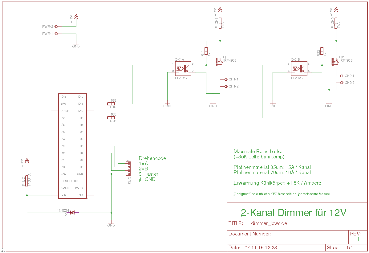
The design is simple: One port (PWR) is used for power supply. It powers the micro controller and the libgtbulbs which are connected to CH1 and CH2. The P-Channel MOSFETs are protected by the fuses F_CH1 and F_CH2. The gates of the MOSFETs are connected to the microcontrollers PWM-able pins D9 and D11 via an opto-coupler. The micro controller is protected by the fuse F_UC and a diode D1 which blows this fuse if plus and minus are reversed. Finally a rotary encoder with an integrated switch is connected to the port ENC.
It is simple to design an appropriate printed circuit board for this:
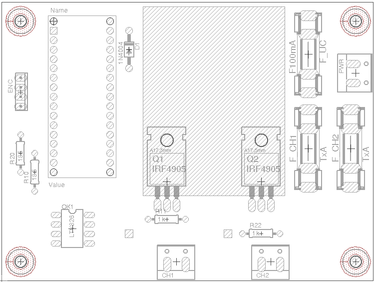
Top layer
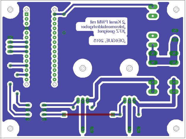
Copper layer (seen from top)
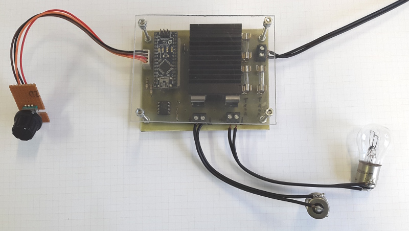
This is how my prototype looks like:
What about the software ?
The software is written with the Ardiono IDE and uses one external library to talk to the rotary encoder. It has the following features:
- Rotating the encoder varies the brightness of the channels.
- Pressing the encoder button for a short time toggles the control of channel A and B.
- Pressing the encoder button for a long time synchronizes channel A+B. This means that the user can modify the brightness of both channels at the same time.
- Doubleclicking the encoder button stores the last dutycycle for each channel in the EEPROM.
- Starts up with the last stored duty cycle
- Bigger increments and decrements of the duty cycle for values > 40%. This makes the feeling more 'natural'.
Final words
I have attached the complete EAGLE schematic and layout to this page. This contains also the needed data sheets for all components and the software.
+-- datasheets
| +-- 187003-da-01-en-PC_827_2XPC817_K827P.pdf
| +-- ArduinoNanoManual23.pdf
| +-- IRF4905.pdf
| \-- irf640n.pdf
+-- DESCRIPTION
+-- eagle.epf
+-- highside_switch
| +-- dimmer_highside.brd
| \-- dimmer_highside.sch
+-- lowside_switch
| +-- dimmer_lowside.brd
| \-- dimmer_lowside.sch
\-- software
+-- Dimmer
? \-- Dimmer.ino
+-- Switch.cpp
\-- Switch.h
Beside the here presented 'low-side switch variant' the file contains another layout named 'highside_switch'. Be warned: This one does NOT work in automotive environments, because it uses an N-Channel MOSFET.
Let me know if you like the design in the comments section.